
📌 Key Takeaways
Build the lift station’s I/O schedule from verified field needs before comparing controllers, or hidden gaps may surface during startup.
Map Every Point: List every pump, sensor, alarm, and signal separately with its purpose, source, and status.
Confirm Signal Compatibility: Signal labels alone do not prove compatibility; qualified reviewers must confirm power, range, isolation, accuracy, and failure behavior.
Trace Every Requirement: Link each point to an operating purpose, sequence reference, requirement source, and reviewer before selecting equipment.
Plan Known Additions: Assign future points to known changes, and support any unassigned spare capacity with a current project requirement.
Review Across Teams: Operations, engineers, controls specialists, and panel designers should review every point before the schedule guides equipment buying.
Visible requirements prevent late surprises.
Lift station owners, engineers, and controls teams will spot planning gaps before using the detailed worksheet guidance below.
~ ~ ~ ~ ~ ~ ~ ~ ~ ~ ~ ~ ~ ~ ~ ~ ~ ~
A proposal that lists forty digital inputs and eight analog channels can look complete and still miss the point. Channel counts describe controller capacity; they don't confirm that every pump, sensor, alarm, and future addition has a documented, traceable requirement behind it. That gap tends to surface at the worst time — during panel review, commissioning, or startup — when an unaccounted-for point forces a change order. Choosing a controller first and filling in I/O requirements afterward can feel efficient, but it lets the chosen product shape the requirements instead of the other way around. A preliminary I/O schedule works in the opposite direction: start from what the station actually does — pumps, wet-well behavior, alarms, and foreseeable additions — before a controller model enters the conversation.
Start With Station Conditions, Not Controller Capacity
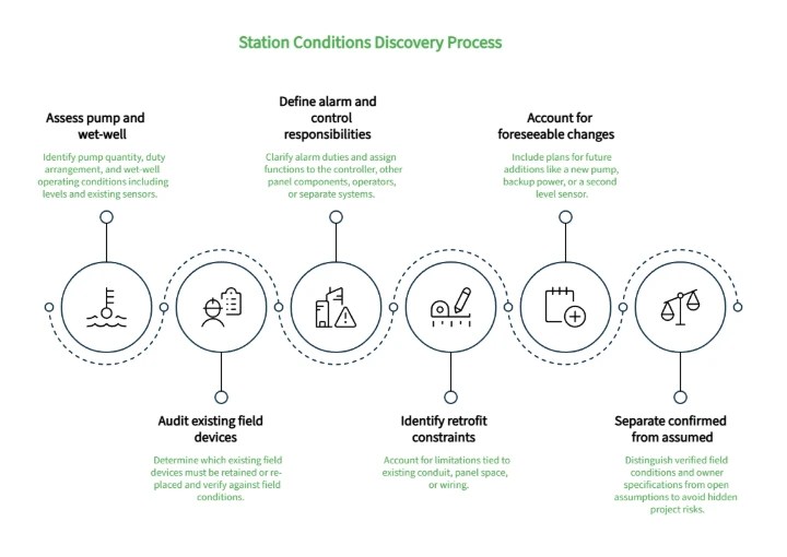
Before anyone counts inputs or outputs, the project team needs a clear picture of what the station does and how it's expected to behave. That picture usually comes from a short discovery pass across six areas: pump quantity and duty arrangement (lead-lag, alternating, standby), wet-well operating conditions (normal range, high and low levels, and any float or transducer already in place), existing field devices that must be retained or replaced, alarm responsibilities the station already carries (high level, pump failure, power loss), which functions belong to the controller versus another panel component, an operator, or a separate system entirely, and any retrofit constraints tied to existing conduit, panel space, or wiring.
Existing drawings and device lists are a starting point, not a finished answer. As-built conditions don't always match the record set, especially on older or retrofitted stations, so field verification belongs in this same pass. Foreseeable changes belong here too — a station slated for an added pump, backup power, or a second level sensor is a different planning problem than one with no expected changes.
The goal at this stage isn't a finished list. It's a clear separation between what's confirmed — verified against field conditions, verified with operations, or specified by the owner — and what's assumed. Carrying an assumption forward as confirmed is a common way a schedule ends up looking complete while quietly hiding open questions.
Build a Device-by-Device I/O Inventory
Once station conditions are documented, the next step is converting each physical condition into a discrete point — a device-by-device inventory, not an abstract exercise.
Each pump typically contributes a run status, a fail or overload status, and possibly a hand-off-auto position. Level sensing contributes its own set — a continuous reading if analog instrumentation is used, plus discrete high- and low-level alarm points if float switches or setpoint contacts are involved. Power monitoring, intrusion inputs, and existing alarm relays add further points. A single physical device rarely maps to a single controller channel, and confirming that mapping is part of the inventory work.
Digital points typically capture or command on/off conditions, such as a pump running or a relay energized, while analog points capture or command a continuous value, such as a wet-well level or pump current draw. An analog output belongs in the inventory only when approved operating requirements and the selected equipment together establish that a variable command is actually needed — it isn't a default category to fill in alongside the other three.
Stakeholders don't always use these terms the same way. "Alarm," "status," and "control" can mean different things to operations, the design engineer, and the controls integrator — and a single condition may need to be monitored, alarmed, reported, and commanded as four distinct responsibilities rather than one blended label — which is one reason each point needs its own row rather than a shared description. A preliminary lift station I/O planning worksheet gives the inventory a consistent structure regardless of whose terminology is used. For each point, record:
Point or tag identifier
Pump, sensor, switch, or field-device description
Condition or function being monitored or controlled
I/O category (digital input, digital output, analog input, analog output)
Expected signal or interface
Normal state or operating range
Abnormal or failure state
Alarm, setpoint, or control purpose
Control-sequence or requirements reference
Requirement source or stakeholder
Compatibility-confirmation owner
Status: confirmed, assumed, or unresolved
Scope classification: retained existing, new base scope, retrofit, future assignment, or spare
Notes and technical-review action
Here is how a wet-well high-level float translates into the worksheet:
I/O Parameter | Example Entry |
|---|---|
Point | DI-04 |
Description | High-level backup float |
Condition | Wet-well overflow risk |
I/O Category | Digital Input |
Expected Signal | Dry contact, normally open |
Normal State | Open (low water) |
Abnormal State | Closed (high water) |
Purpose | Trigger local alarm beacon and backup pump call |
Sequence Reference | Sec 2.1.4 (Overflow Response) |
Requirement Source | Municipal Standard Specs |
Confirmation Owner | Controls Integrator |
Status | Confirmed |
Scope | New base scope |
Consider a small hypothetical duplex station: two pumps, a submersible level sensor, and a high-level float. The worksheet would carry separate rows for each pump's run and fail status, the level reading, the high-level alarm, and any existing power-loss input. OmniSite's Station Utilization Score page describes analog water-level and pump-current readings, runtime, inflow/outflow reports, digital states, and alarms as examples of commercial monitoring data, and the Kits page similarly lists pump amp probes, a submersible level transducer, and optional radar level sensing as product-specific field-device examples. Both illustrate point variety, not a template to copy directly into a worksheet.
Classify the Point, Then Confirm the Interface
Labeling a point "analog input" or "digital output" answers what kind of signal is expected. It says nothing about whether that signal will actually work with the controller once it's installed.
Two points in the same I/O category can still differ in ways that matter: source power (dry contact versus powered), signal range, isolation requirements, accuracy needs, and how each device behaves in a failure state. A 4–20 mA level transducer and a lower-voltage analog sensor are both "analog inputs," but they aren't interchangeable without confirming the controller's accepted input range. A dry-contact float switch and a powered alarm relay are both "digital inputs," but one may need an isolated input and the other may not.
Classification | Compatibility | |
|---|---|---|
Answers | What kind of signal is this? | Will this signal work with this controller? |
Confirms | I/O category (digital/analog, input/output) | Source power, range, isolation, accuracy, normal/failure state |
Source | General device function | Current manufacturer documentation and qualified technical review |
The worksheet's signal/interface, normal-state, and failure-state fields exist to carry this second layer of confirmation. For each point, the project team should record what's expected, then assign a compatibility-confirmation owner who checks that expectation against current manufacturer documentation for the specific pump, sensor, or switch involved. That owner typically follows the category involved: an electrical or controls reviewer for digital inputs, controls and panel-design reviewers for digital outputs, an instrumentation, electrical, or controls reviewer for analog inputs, and both the engineer and controls reviewer together for analog outputs, since those carry an approved-need question on top of the usual interface questions.
Treating classification as the finish line is one of the more common ways a proposal looks technically sound while leaving compatibility questions unresolved until commissioning. A point that's correctly categorized but electrically unconfirmed is still an open item, not a completed one — and a correct data sheet cannot resolve a mismatched tag or an undocumented equipment replacement.
Link Every Point to Setpoints, Alarms, and the Control Sequence
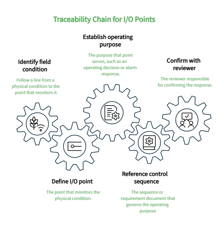
A point isn't fully defined by its category and interface alone. It also needs a documented purpose: what operating decision, alarm response, or control action depends on it.
Requirements traceability means being able to follow a line from a physical condition to the point that monitors it, to the purpose that point serves, to the sequence or requirement document that governs that purpose, and finally to the reviewer responsible for confirming it:
Field condition → I/O point → Operating purpose → Control-sequence reference → Reviewer
A wet-well high-level condition, for example, traces to a level point, then to a high-level alarm purpose, then to whatever sequence-of-operations document specifies the required response, then to the engineer or operations lead who reviews that response.
This traceability matters most for interlocks, permissive, and command points, where an incomplete link can leave real ambiguity about what the controller should do and when. Documenting that a pump-fail alarm exists is not the same as documenting what happens after it fires, who's notified, or whether a standby pump is expected to start automatically. Those decisions belong to the station's operating philosophy and approved sequence of operations — not to a generic planning worksheet.
The worksheet's control-sequence-reference and requirement-source fields exist to hold this connection, even before specific thresholds or logic are finalized. Recording that a point "requires a documented alarm response, pending sequence-of-operations review" is a legitimate and useful entry. Recording a specific delay, priority, or setpoint value without an approved source behind it is not — those decisions depend on the station's operating philosophy, owner requirements, and qualified engineering review.
Working through the traceability chain also gives reviewers three practical checks to run against the inventory. A point with no stated purpose is worth questioning outright — if nothing depends on it, it may not belong in the schedule. An alarm with no documented response or assigned owner is a gap that needs to be flagged rather than left implicit. And a sequence step that depends on a condition with no candidate point behind it needs to be resolved before equipment selection, not discovered afterward.
Reserve Capacity for Foreseeable Changes
Future capacity gets planned well when it's tied to identified changes, and poorly when it's reduced to a percentage.
An arbitrary spare-I/O allowance — adding a flat percentage or rounding up to the next chassis size — can look like conservative planning while actually concealing incomplete requirements gathering. If the station is genuinely expected to add a pump, replace an aging level sensor, or bring on backup power in the next few years, those are known future points, not spare capacity, and they belong in the schedule as such.
A more useful approach separates several categories: points already required for current operation, points tied to a specific, identified future change, points that will exist only because equipment is being replaced with a different interface or a documented retrofit phase adds scope, and capacity that is genuinely unassigned. Working through that separation raises the right questions:
Is an additional pump, level device, or alarm point already planned or under discussion?
Is a power or backup-power status change anticipated?
Is added flow or current sensing being considered — a future flow measurement point, for instance?
Will any equipment be replaced with a different interface, or does the retrofit scope add points outside base scope?
Does the retrofit scope include known but undocumented legacy points?
Has the owner specified a capacity allowance, and if so, from what current standard or project document?
Any specific percentage or quantity requires a current owner, authority, or project source behind it. The worksheet's scope-classification field exists to keep retained-existing, new-base-scope, retrofit, future-assignment, and spare points distinct rather than folding everything into one undifferentiated total.
Review the Schedule Across Disciplines Before Procurement
A preliminary I/O schedule is only as reliable as the number of people who've checked it. No single stakeholder holds every piece of the requirement.
Reviewer | Confirms |
|---|---|
Operations | Device existence, current operating intent, retrofit conditions |
Consulting engineer | Requirements traceability, sequence references, alarm purposes |
Controls specialist | Signal compatibility, interface characteristics, confirmation status |
Panel designer | Constructability, spare-field allocation, scope boundaries |
Authority or owner reviewer (where applicable) | Applicable code, jurisdictional, or design-standard requirements |
This isn't a fixed contractual structure — roles and review sequences vary by project — but the principle holds across projects: before the schedule informs procurement, every point's existence, purpose, and compatibility status should be checked by someone qualified to confirm it. A completed worksheet remains a preliminary planning record. It does not replace approved plans, specifications, calculations, site investigation, manufacturer documentation, or authority review.
Frequently Asked Questions
How much spare I/O should a lift-station controller include?
There's no universal percentage that fits every project. Start by identifying specific future devices and changes the station is likely to need, then document any additional spare allowance based on a current owner, authority, or project requirement — not a rule of thumb.
Is identifying a point as analog or digital enough?
No. Classification confirms the type of signal; it doesn't confirm that the signal will work with the controller. The project team still needs to verify interface characteristics, normal and failure states, and compatibility using current manufacturer documentation and qualified technical review.
When is a preliminary I/O schedule ready for equipment comparison?
When the known points, their purposes, remaining assumptions, unresolved interfaces, sequence references, and foreseeable additions are all visible enough for stakeholders to review together. It's still a planning tool, not a substitute for final engineering documentation.
Use the Schedule as a Review Tool
A preliminary I/O schedule's value isn't completeness — it's visibility into gaps early. Review it with operations, the consulting engineer, controls personnel, and the panel designer before using it for equipment selection or project documents. For related context, see OmniSite's wastewater management overview.
Disclaimer: This article is for general informational purposes only and does not constitute compliance, safety, technical, or professional advice. Requirements, risks, and best practices may vary by context, jurisdiction, system, provider, or use case. Confirm important decisions with the appropriate qualified professional, authority, or technical expert.
Our Editorial Process:
Content is developed from OmniSite source materials and reviewed for clarity, usefulness, and factual consistency. It is intended to help municipal and utility professionals evaluate monitoring and response-readiness options and should not replace site-specific engineering, electrical, regulatory, or safety guidance.
By the OmniSite Insights Team
The OmniSite Insights Team turns field-tested monitoring, alarm-notification, and municipal infrastructure knowledge into practical guides for wastewater, water, and remote equipment teams. OmniSite manufactures control systems that support early warning for lift stations, water systems, wastewater systems, and airfield lighting applications.