
📌 Key Takeaways
A prevention plan only works when it becomes a tested alarm path people can trust.
Start With One Station: Choose one high-risk lift station first, then use that setup as the rollout model.
Pick Alarms Early: Define key alarms before installation so the device tracks what truly needs attention.
Match The Hardware: Monitoring and backup pump control need different device features, so decide the station’s role first.
Check The Site: Confirm signal, power, antenna placement, and trained staff before the crew starts work.
Test Every Alert: Prove the alarm reaches the right people before calling the station fully live.
A mounted box is not protection; a tested response path is.
Municipal wastewater teams moving from planning to live monitoring will get a clear first-step framework, setting up the implementation guide below.
~ ~ ~ ~ ~ ~ ~ ~ ~ ~ ~ ~ ~ ~ ~ ~ ~ ~
An overflow prevention plan that lives in a binder does not stop a wet well from rising. At some point the plan has to become a device on a wall, a wire on a terminal block, and a phone that rings when something goes wrong. This checklist carries a municipal wastewater team across that gap: from choosing the first lift station, to defining the data that matters, to activating and testing a working alarm path.
It is written for two readers at once — the utility director who needs a low-risk decision path, and the field technician who needs a clear list of what to verify before calling the job complete. OmniSite, which manufactures the wastewater monitoring systems referenced throughout, frames its work around a simple mission: early warning at municipal lift stations helps protect drinking water, waterways, and the communities downstream of a failure. That mission only matters once equipment is installed, activated, and proven to work.
Why Cellular Telemetry Comes After the Plan, Not Instead of It
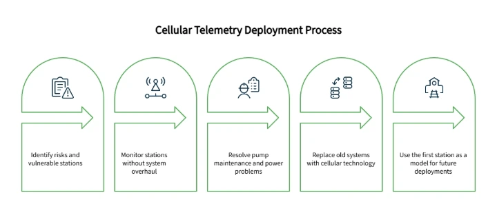
A written plan identifies risk. It does not reduce it. The plan merely highlights vulnerable stations; cellular telemetry actively monitors them without requiring an expensive, full-system overhaul.
A meaningful share of sanitary sewer overflows nationally are linked to inadequate pump maintenance and a lack of backup power, according to the U.S. Environmental Protection Agency — a reminder that visibility into pump condition is a recognized risk factor, not a cosmetic upgrade. Wastewater collection systems carry domestic, commercial, and industrial wastewater to treatment facilities, and a sanitary sewer overflow along that path can quickly become a public health and environmental concern, which is the broader reason early detection earns this kind of attention from regulators and utilities alike.
Many utility teams are still managing stations on legacy SCADA setups, hardwired phone lines, or radio links that degrade quietly for months before anyone notices. The shift to cellular is something like trading a fragile landline for a rugged smartphone: both relay information, but only one keeps working when conditions are less than ideal. Cellular telemetry will not fit every site, but for a team avoiding an expensive rip-and-replace project, it is often the simplest first move — a self-contained unit, a cellular connection instead of a buried line, and software that does not require an in-house programmer.
This checklist treats the first deployment as a model rather than a one-off. Get a single station right, and the same sequence becomes the rollout plan for every station that follows.
Step 1: Choose the First Lift Station
The decision starts with prioritization, not technology. Effective lift station monitoring begins with picking the right first site, not the most stations at once. A reasonable first candidate has a documented history of high-water alarms or known wet well risk, depends on aging telemetry or a weak communication path, has limited after-hours visibility, and carries meaningful consequences if something is missed — and it should be practical to deploy quickly, not the most complicated station in the system. How to Build a Fail-Safe Wet Well Monitoring Strategy in 3 Steps covers risk scoring in more depth for teams weighing several candidates.
It also helps to capture a few practical details while scoping that station: project city and state, station type, and whether the team already knows which hardware fits. Uncertainty here is normal — a Quick Quote request routes those questions to a local representative who specializes in matching stations to the right device, using project location to connect the request with someone who can help.
Step 2: Define the Alarms and Data That Actually Matter
Once a station is chosen, the prevention plan needs to be translated into specific inputs: high wet well level, pump overload, phase failure, runtime, cycle counts, flow in GPM, well inflow rate, and rainfall history where applicable, along with a decision on whether notifications arrive by email, text, or voice call.
These should be separated into three categories rather than treated as one list. Critical alarms demand immediate awareness — a high wet well level or a pump overload. Operational data is different: it helps a team catch a developing problem before it becomes an alarm, the role runtime and cycle trends play. How to Spot Impending Lift Station Failures in Pump Data Trends explains how that trend data gets used in practice. The third category, reporting cadence, is simply how often the team wants a summary rather than an alert. None of this requires a wiring diagram — only a decision about what is worth wiring in at all, alongside baseline system-health checks such as signal strength and battery status.
Defining this list before field day also prevents a common mistake: buying monitoring hardware before deciding what the station actually needs to report. An installer who reaches the panel without that decision made in advance often discovers the expected data depends on wiring, sensors, current switches, or level inputs that were never planned for. Writing the alarm list down alongside the station name, panel notes, and callout contacts — even on a clipboard — keeps that decision from getting made on the fly.
Step 3: Monitoring Only, or Backup Pump Control
Not every station needs the same capability, and the central planning question is straightforward: does this station need visibility alone, or does it also need control redundancy?
Station Need | Planning Question | Likely Capability Area |
|---|---|---|
Know when high wet well occurs | What alarms must trigger immediate response? | Alarm monitoring |
Track runtime and cycles | What pump behavior should trend over time? | Reporting and trend history |
Monitor level | Does the team need analog level insight? | Analog inputs |
Add backup pump control | Does the station need control redundancy? | Relay outputs and controller capability |
A station mainly needing reliable alarm visibility and trend awareness typically fits a lift station alarm device built around ten universal digital inputs, designed to monitor alarm conditions and analyze trends such as runtime, GPM, and pump cycles. A station that also needs analog level monitoring, relay outputs, or backup pump control calls for a different tier: a cellular pump station monitor and lift station controller of this type generally offers fourteen digital inputs, four analog inputs, and four relay outputs — enough to monitor level and run backup pump control from a single unit. An unclear fit is a legitimate starting point, not a problem to solve before reaching out.
That second question, about control redundancy, changes the conversation beyond hardware selection. It can affect panel review, wiring scope, and who needs to be involved before installation even begins — which is part of why this decision belongs early in the process rather than at the panel.
Step 4: Confirm Site Readiness Before Installation
This step stays at the level of planning rather than a full installation manual, but a few field realities are worth confirming before a crew arrives with a finished unit and no place to put it. Cellular reception should be confirmed at the station itself, not assumed from a coverage map — Verizon's ThingSpace coverage documentation notes that published coverage maps are predicted and approximate, and that terrain, buildings, foliage, weather, and customer equipment can all affect actual service at a given site. Power source and backup expectations need to be settled, along with whether the unit will mount indoors, outdoors, or inside an existing control panel. Antenna placement deserves particular care: when a unit goes into an existing electrical cabinet, antenna coax should not be routed alongside high-voltage cable or alarm horn power wiring, since that pairing can cause unpredictable reception or damage the radio circuit, and the antenna itself should be positioned where a metal enclosure will not block it. Aging or unreliable alarm wiring is worth replacing at this stage rather than working around — Replacing Outdated Alarms: A Checklist for Lift Station Overflow Prevention covers that decision separately.
No cellular system can promise flawless performance under every condition — signal depends on the device, installation, antenna, terrain, and surrounding environment. Some teams specifically worry that cellular networks will fail during the same storms that cause the worst overflows; the reasonable response is to plan around that, not dismiss it — confirm backup power, verify signal strength during deployment rather than assume it, and build a secondary contact into the alarm escalation path. This kind of work should always go to qualified personnel, a distinction OSHA's general industry electrical standards define in more detail, particularly around work near exposed energized parts.
Step 5: Activate the Unit Before the Crew Arrives
A finished installation that cannot yet communicate with GuardDog is a wasted truck roll. Activation should happen before the crew is on site, and it is not instantaneous: OmniSite's quick-start guidance indicates activation can take up to one full business day, with activation recommended one to two days ahead of installation. Readiness items worth confirming beforehand include the unit ID, cellular service plan, billing and account details, the primary GuardDog user credentials, the project contact, any purchase order or service reference, the planned install date, and who should receive the activation confirmation — a short sequence that keeps a mounted, wired unit from sitting idle. A successful field day starts the day before, not the morning the crew shows up to an open panel and an account that's still being set up.
Step 6: Configure GuardDog Callouts and Reporting
Hardware mounted on a wall does not help anyone if no one finds out when it goes into alarm. GuardDog is OmniSite's secure, cloud-based notification system and historian, included at no extra charge with any OmniSite product, and it converts a wired input into an alert someone receives. It supports reporting, customizable callout lists, map-view alarms, alarm triggers, historical data, and report exports. Setup generally involves adding recipients to the recipient library, creating a callout list and schedule, and configuring the alarm triggers. From there, confirm which events notify by phone, text, or email, who acknowledges an alarm, and the preferred reporting cadence: standard service delivers a report every twenty-four hours, while Elite steps that up to fifteen-minute analog reporting, with alarms themselves always sent in real time.
A callout list is an operating procedure in software form, not just a contact list, so it's worth confirming who specifically receives high wet well alarms, who handles battery status notifications, who reviews communication checks, and who should know if a maintenance key disables a device. The answer should match the utility's actual response plan rather than the first few names someone remembered during setup. A unit wired correctly but never connected to a callout list is not really monitoring anything.
Step 7: Validate the Alarm Path Before Calling It Complete
This is the step teams are most likely to skip, and it is the one that actually proves the work. Mounting a unit is not the finish line; confirming an alarm reaches the right person is. That means triggering the agreed alarm condition through approved procedures, confirming it appears in GuardDog, and confirming the correct contacts are notified and acknowledge it. Reviewing the alarm wording itself matters too, so the person on call knows which station needs attention and what condition triggered the notice. Battery condition and text notification capability are worth checking here as well, since they are worth revisiting periodically once the station is live.
The result should be documented — station name, tested alarm, date, technician, notification recipients, response method, and any corrections made — both as a template for the next station and as the line between "a box is mounted" and "a response path has been proven." The EPA's CMOM guidance for collection systems emphasizes exactly this kind of management, operation, and maintenance recordkeeping, and a short, reliable validation record serves that purpose better than an elaborate form nobody actually fills out. The outcome is a working notification system, not a guarantee that every future loss is now impossible.
Printable Transition Checklist
This section condenses the steps above into a single working reference. It can be printed, handed between leadership and field operations, or reused as the template for the next station.
Station Selection
Identify the first high-risk station for cellular telemetry.
Record project city and state for representative routing.
Note whether the product fit is already known or needs guidance.
Alarm and Data Requirements
List alarms requiring immediate notification.
Separate critical alarms from operational trend data.
Confirm the desired reporting cadence.
Match each desired report to the wiring, sensor, or configuration step it depends on.
Hardware Fit
Decide between monitoring only and backup pump control.
Confirm digital, analog, and relay requirements against the chosen device.
Installation Readiness
Confirm cellular reception and power/backup expectations.
Plan antenna placement away from high-voltage or alarm horn wiring, and clear of metal obstruction.
Confirm qualified personnel are scheduled for the work.
Activation Readiness
Confirm unit ID, account information, and project contact.
Select the cellular service and reporting level.
Note the purchase order or service reference and planned install date.
Submit activation one to two days ahead of installation.
Confirm who receives the activation confirmation.
GuardDog Setup
Add recipients and build a callout list and schedule.
Configure alarms and confirm notification routing.
Confirm who is responsible for each alarm type, including battery status and communication checks.
Alarm Path Validation
Trigger or simulate the alarm condition.
Confirm notification reaches the correct contacts and is acknowledged.
Document results (station, alarm, date, technician, recipients, response, corrections) as the model for the next station.
Next-Station Rollout
Decide whether training or setup support is needed before expanding.
Use this checklist to identify the first station, then contact OmniSite to confirm the best monitoring or control path for that specific site.
What to Do After the First Station Is Live
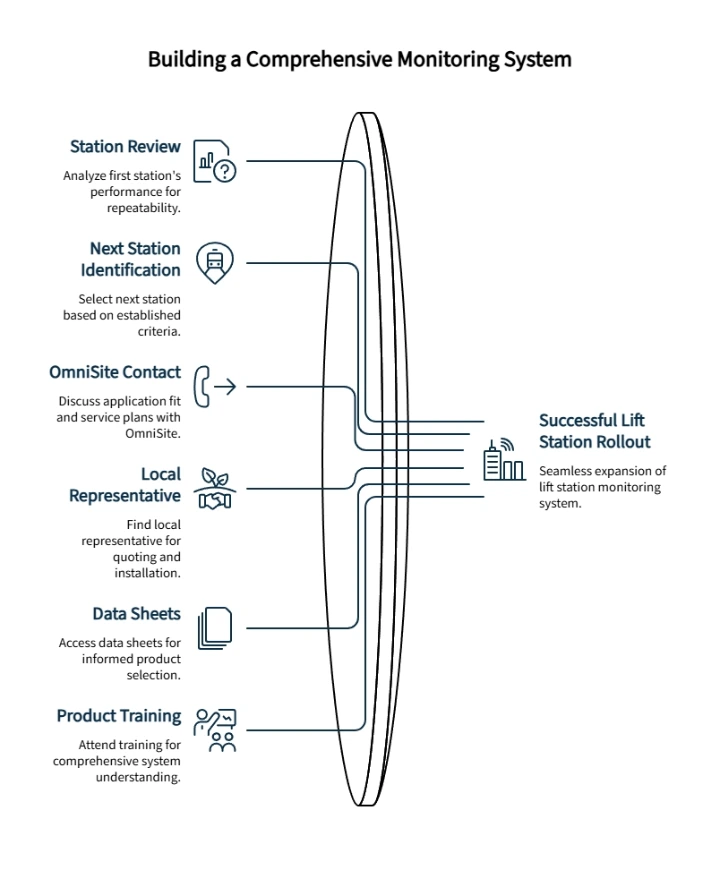
Once the first station is live and the alarm path is confirmed, the work shifts from setup to repeatability. Reviewing how the station's alarms and reports behaved over the first few days — GuardDog's historical data and report exports make that comparison straightforward — then identifying the next station using the same criteria from Step 1, turns this checklist into a genuine rollout template. The First 48-Hour Blueprint: Launching Your Lift Station Overflow Prevention Plan walks through that next sequence.
When a team is ready to move from evaluation toward procurement, contacting OmniSite to discuss application fit is a natural next step. A Quick Quote request connects a project to a local representative based on project state, covering product selection, service plans, and configuration support in one conversation. Teams ready to work with a partner who can quote, install, and help get units in hand can find a local representative the same way, and those needing data sheets or specs first can access that literature through the Documents page without committing to a purchase. For organizations scaling beyond a station or two, OmniSite also offers free, in-person, 1.5-day product training in Indianapolis, covering wiring, installation, activation, troubleshooting, and the GuardDog interface — a support option for growth, not a prerequisite for starting.
A prevention plan only protects what it actually monitors. One tested station, with a documented alarm path and a clear rollout model, does more for a cloud based wastewater monitoring system than another round of planning ever will.
Frequently Asked Questions
What should a lift station cellular telemetry transition checklist include?
A transition checklist should cover station selection, alarm and data requirements, hardware fit, cellular signal review, activation timing, GuardDog setup, alarm-path validation, documentation, and the plan for rolling the process out to the next station.
How should a team choose between monitoring only and backup pump control?
Start with the station's purpose. If the priority is alarm visibility, a monitoring-focused device like the XR50 may be enough. If the site also needs backup control capability available locally, a control-capable option like Crystal Ball is the better fit.
Disclaimer: This article is for general planning and educational purposes only. Lift station electrical work, telemetry installation, control panel wiring, and wastewater infrastructure work should be performed by qualified personnel following applicable codes, site procedures, manufacturer documentation, and local requirements. OmniSite product selection and configuration should be confirmed with OmniSite or an authorized representative before deployment. OmniSite products and services support monitoring, notification, and response readiness, but they are not insurance and do not guarantee that property loss, personal injury, overflow, service interruption, or other loss will never occur. Cellular service, message delivery, device performance, antenna placement, installation conditions, and environmental conditions can affect operation.
Our Editorial Process:
Content is developed from OmniSite source materials and reviewed for clarity, usefulness, and factual consistency. It is intended to help municipal and utility professionals evaluate monitoring and response-readiness options and should not replace site-specific engineering, electrical, regulatory, or safety guidance.
By the OmniSite Insights Team
The OmniSite Insights Team turns field-tested monitoring, alarm-notification, and municipal infrastructure knowledge into practical guides for wastewater, water, and remote equipment teams. OmniSite manufactures control systems that support early warning for lift stations, water systems, wastewater systems, and airfield lighting applications.